STEP 1: MEASURE
The first step in making your own table saw guide rail is to measure the table and extension table. Angle iron is almost always shorter than tubing in guide rail design builds. The angle iron is generally cut to the exact length of the cast iron saw plus the extension table. The rectangular tubing will over hang on each end; up to 6 inches total overhang on short guide rails and up to a foot total on longer guide rails e.g. 7″ right 5″ left.
NOTE: If you still aren’t sure about your specific guide rail requirements, watch AskWoodMan’s short video: How To Determine Your Guide Rails Specs.
")
STEP 2: GET YOUR STEEL
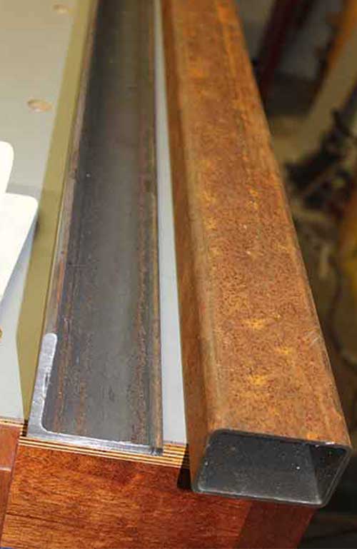
You will need 3x3x1/4″ angle iron and 3×2″ 11 gauge tubing.
NOTE: If you buy full lengths of steel you can often get a much better price. But if you don’t have a good way to transport long lengths and/or cut your steel, go ahead and let them cut it to your exact measurements. (fig.2a, 2b)
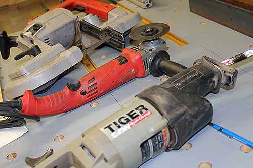
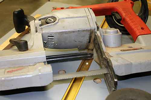
STEP 3: CUT STEEL TO LENGTH
If the steel supplier didn’t cut your steel to length, you will need to cut it yourself before you begin. Common cutting options for steel are a Portaband, angle grinder with cut off wheel, or sawzall with bimetal blade. Metal cutting chop saws will also work. (fig.3a, 3b, 3c, 3d)


STEP 4: CLEAN STEEL
Remove rust and scale with 3M Scotchbrite abrasive disc mounted on an angle grinder.
NOTE: Cleaning the steel needs to be done if you plan on priming and painting yourself. Cleaning the steel at the beginning of the project makes the whole fabrication process less dirty and grimy. If you plan to have the guide rail professionally powder coated, don’t waste your time cleaning because they will sandblast the steel to bare metal. (fig.4a)

Cleaning steel (fig.4a)
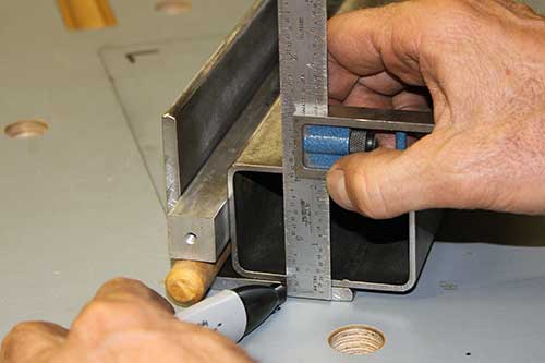
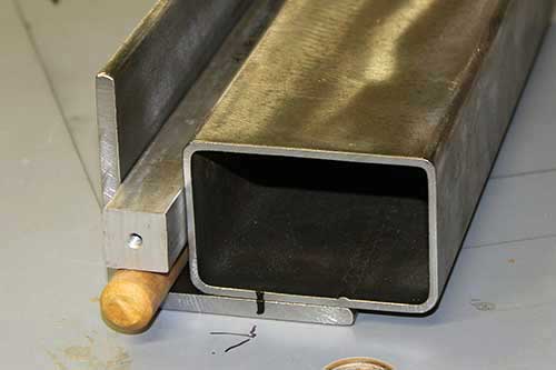
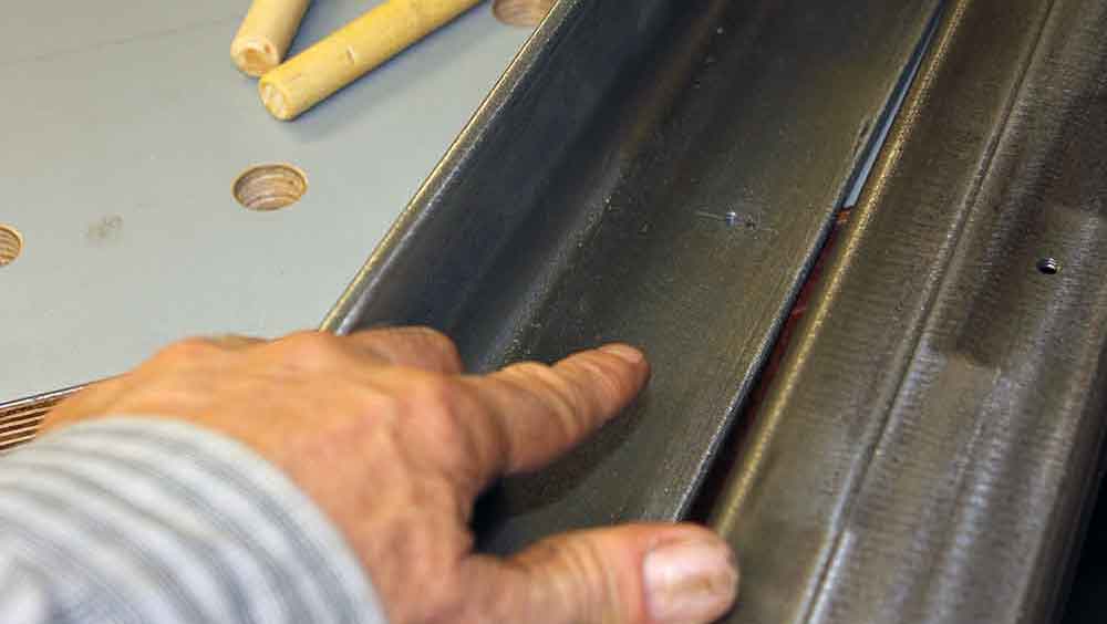
STEP 5: EXAMINE TUBING
Examine your tubing in relation to the angle iron. Look for the interior weld bead. You’ll want to make sure that the weld bead is down and away from where the bolts will be connecting the angle iron to the tubing. The reason you want the bead on the bottom of the tubing is because sometimes there will be a slight distortion near the weld and you want the perfectly smooth surface on the top of your tubing guide rail. (fig.5a)
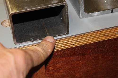
Find the weld bead and avoid (fig.5a)
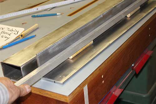
STEP 6: PARALLEL SPACING SET UP
Get your parallel spacing set up ready. You can use a long 3/4” bar or blocks for parallel spacing and blocks or dowels will work for lifts. You could have more than 3/4″ gap if necessary, but not less. 3/4″ is the absolute minimum spacing you need to have and it but be perfectly parallel.
NOTE: I used a long aluminum bar and old paint brush handles to act as a bar lift. It’s important to lift the parallel spacer a little bit so that the inside radius of the angle iron does not interfere with spacer alignment. (fig.6a, 6b, 6c)

Parallel Spacing Set-up (fig.6a)
Parallel Spacing Set-up (fig.6b)
Parallel Spacing Set-up (fig.6c)
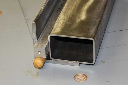
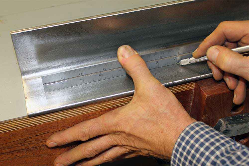
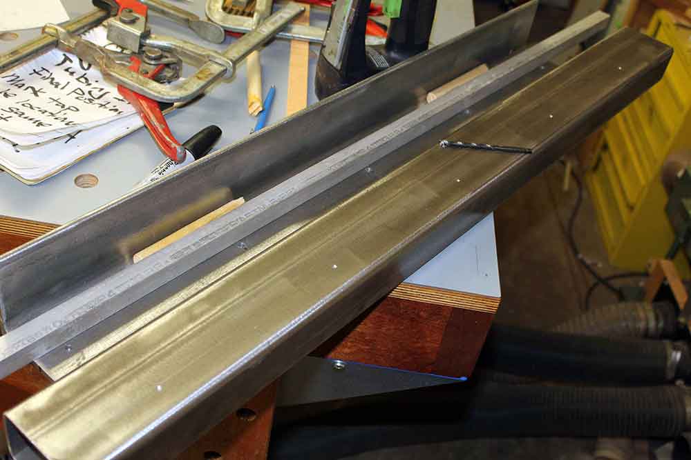
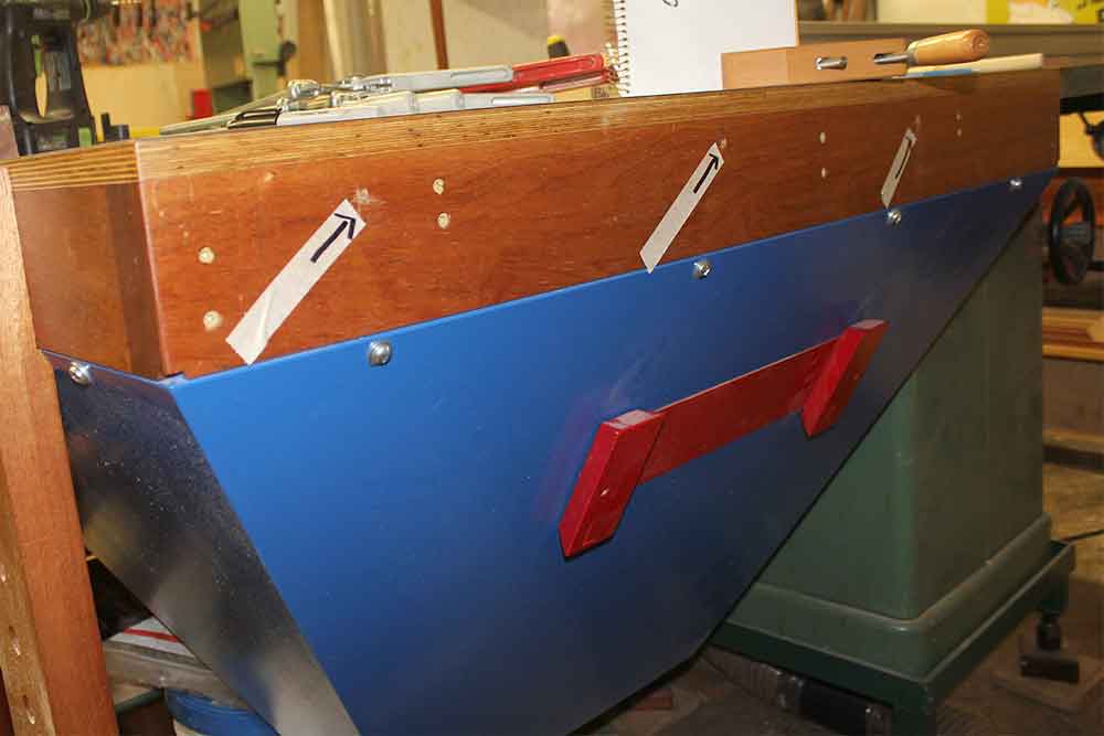
STEP 7: MARK BOLT LINE ON BOTH
With your parallel spacer in place, mark the bolt line on one end of the tubing and bottom of the angle iron. Exact position isn’t critical for this, it doesn’t need to be centered, just pick a location that looks good and avoid the weld bead. This is your first reference for bolt placement. Each bolt location will be marked with intersecting lines in step 9 for exact drilling. (fig.7a, 7b, 7c)
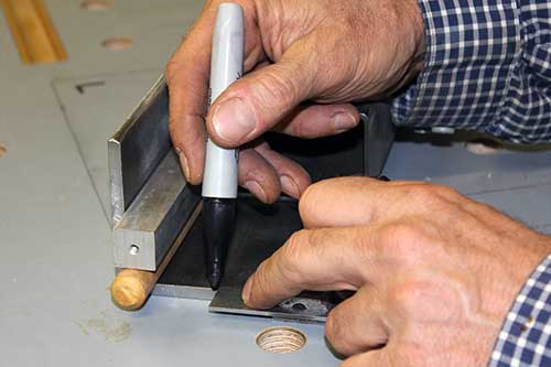
With parallel spacing in place, mark bolt center line on angle iron (fig.7a)
Marking bolt center line on tubing / angle iron (fig.7b)
Step 7 complete, both iron and tubing marked (fig.7c)
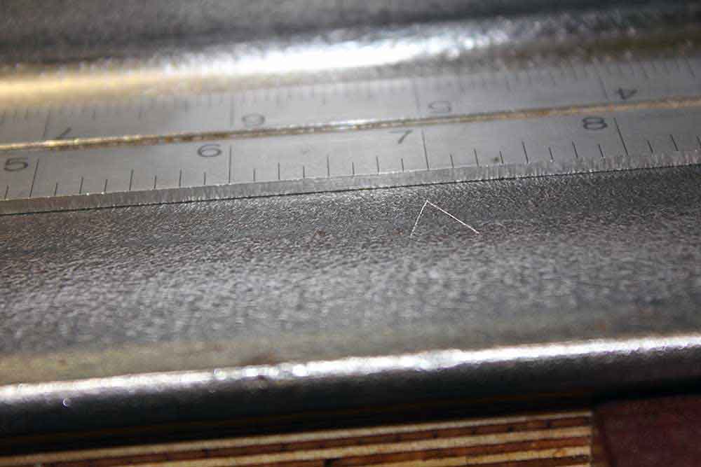
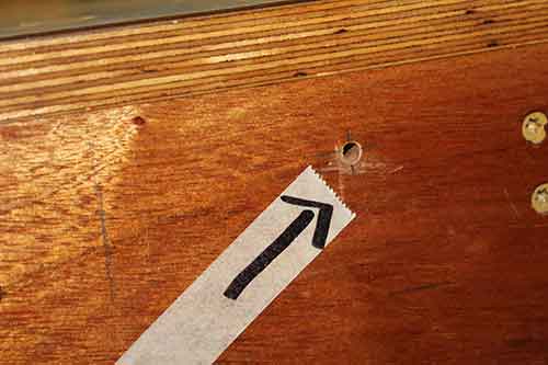
STEP 8: DRAW ANGLE IRON HOLE SPACING LINES
Lay out the hole location along the bolt line on the angle iron using a ruler or tape. Start by marking lines 1″ in from each end. Then equal spacing between the 1” inset lines, not to exceed 10 inches apart. When you are done you’ll have several lines perpendicular to the length of the angle iron.
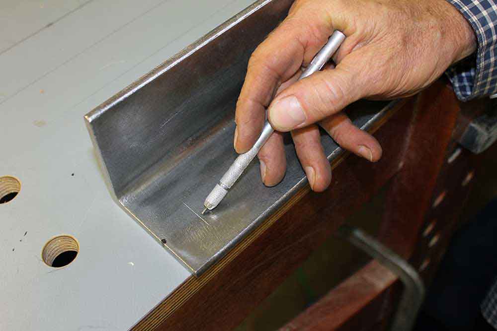
NOTE: I mark the interior spacing locations with a scribed V and then come back in and draw a generous line through the point of the V with my combination square. (fig.8a, 8b, 8c, 8d, 8e)
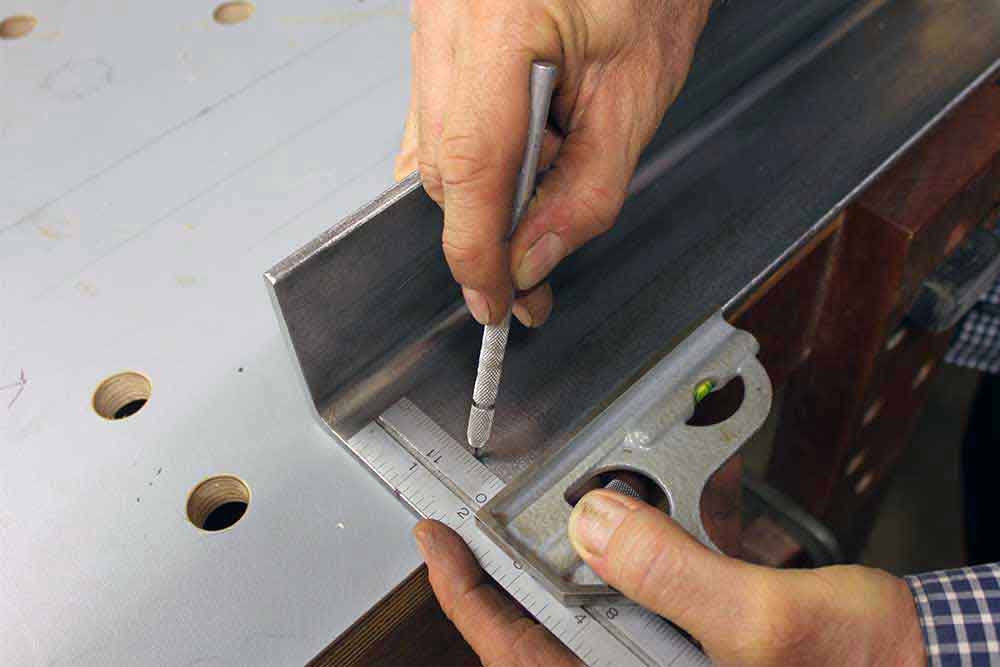
Using a scribe to mark 1 inch inset on angle iron (fig.8a)
Pointing to inset scribe mark on angle iron (fig.8b)
Marking a V at the second bolt hole location on angle iron (fig.8c)
Close up of scribed V pointing to the exact bolt location (fig.8d)
Drawing a line through the V with your scribe (fig.8e)
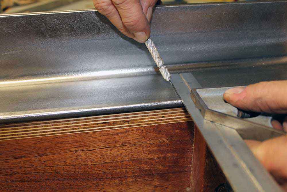
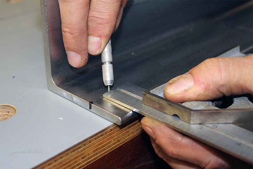
STEP 9: MAKE EXACT DRILL MARKS ON ANGLE IRON
Use a combination square and a scribe to mark your exact bolt locations. Make a scribe mark parallel to the length of the angle iron at each one of your marked drill locations. These intersecting lines (cross marks) on angle iron will be center punched for drill location. (fig.9a, 9b, 9c)
Scribing intersection line, parallel to angle iron length (fig.9a)

Marking complete, pointing to exact bolt location (fig.9b)

Using a center punch to make a mark for the drill bit to start (fig.9c)
It’s easy to make your own table saw guide rails, all you need is a little direction and a few crucial measurements.
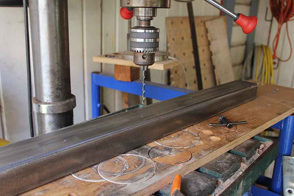
STEP 10: DRILL FIRST HOLE SIZE ON ANGLE IRON
Using the drill press, drill these marked locations in the angle iron with a #7 twist drill bit. Drill all the way through.
NOTE: A 13/64” will also work if a #7 is not available. (fig.10a)
Drilling holes all the way through with a #7 twist drill bit (fig.10a)
STEP 11: CLAMP TUBING TO ANGLE IRON
Clamp the tubing to the angle iron with your parallel spacing in place using your four clamps. This is where you decide the exact tubing overhang you want at either end. Be sure your 3/4” parallel spacer is properly in position with no interference.
NOTE: First you will clamp in final position (fig.11a) and then flip the clamped assembly upside down (fig.11b) in preparation for using the #7 drill bit to mark tap holes.
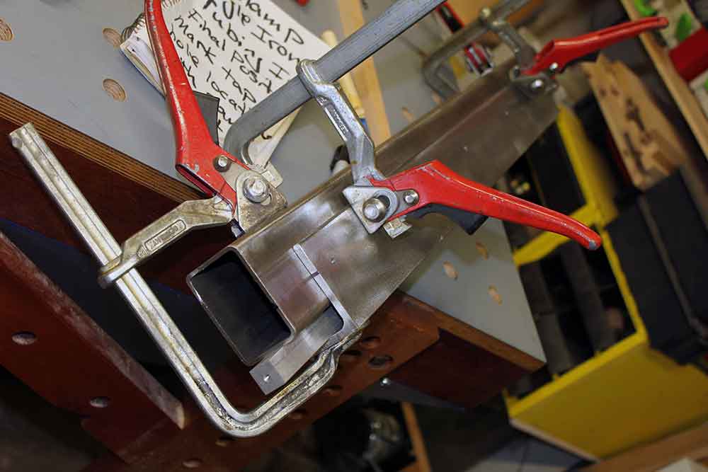
Flip clamped unit upside down to mark drill locations in tubing through angle iron holes (fig.11b)
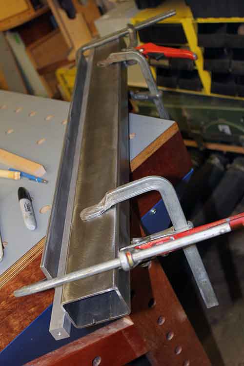
With parallel spacing in place, clamp angle iron to tubing and determine overhang (fig.11a)
STEP 12: DRILL MARKS ON TUBING
Put the #7 drill bit in a hand held drill and use the already drilled holes in the angle iron as your template. Drill through the holes in the angle iron and mark on the tubing. You don’t need to drill all the way through the tubing. You are just making drill location marks. (fig.12a)

Drilling through the holes in the angle iron to mark drill tap locations on tubing (fig.12a)
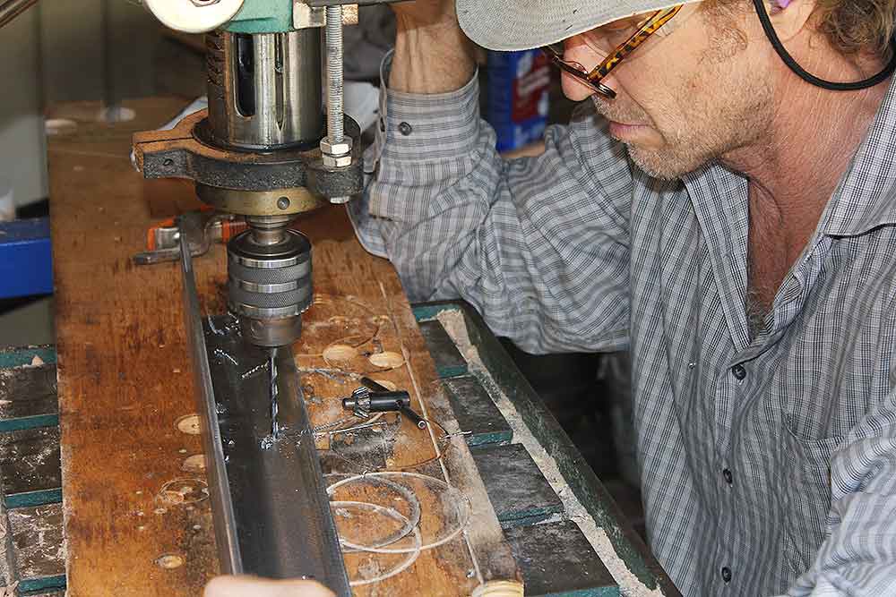
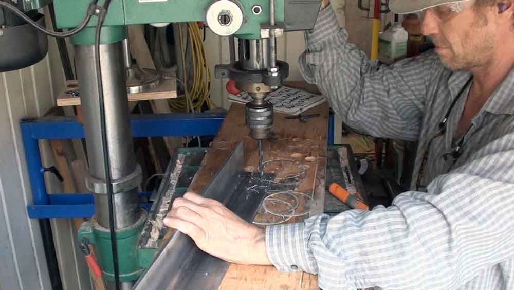
STEP 13: UNCLAMP AND DRILL HOLES IN TUBING
Take the clamps off and take the tubing to the drill press. Drill through the tubing with the #7 drill bit on the drill marks. This is when you drill all the way through the marked side of the tubing. (fig.13a, 13b)
Unclamp tubing from angle iron (fig.13a)
Drill holes through marked location on tubing with #7 drill bit (fig.13b)
STEP 14: TAP HOLES IN TUBING
Now tap these #7 holes in the tubing with a 1/4” 20TPI tap. There are a variety of tools and methods to drive a tap. (fig.14a, 14b, 14c)
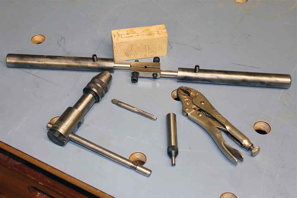
Tap wrench, ratcheting tap wrench, spring loaded tapping center and vise grips (14a)
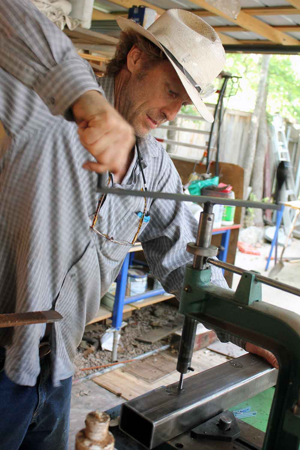
Using a hand tapping machine to tap holes in tubing (fig.14b)
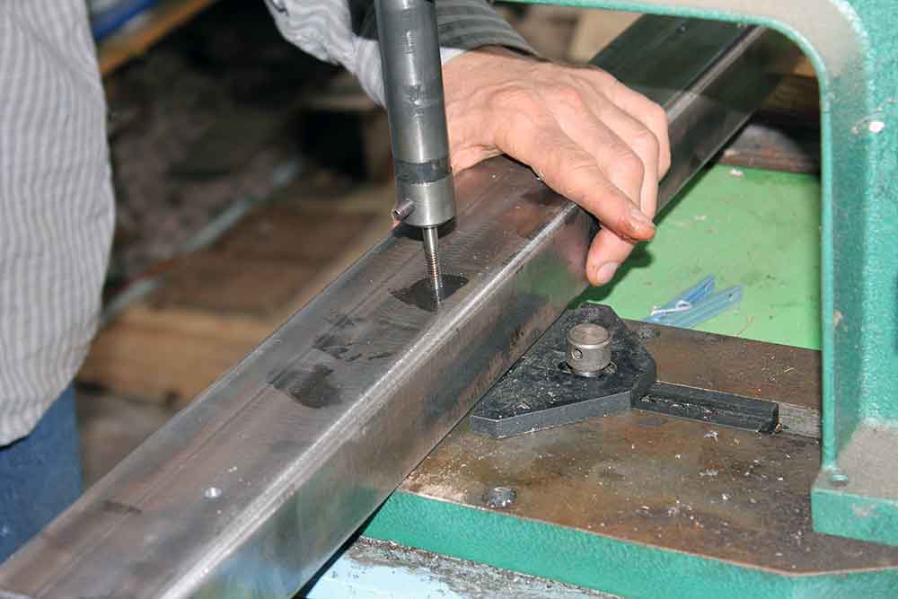
Close up view of tapping holes with hand tapping machine (14c)
STEP 15: DRILL HOLES IN ANGLE IRON
Drill out the #7 holes in the angle iron to 5/16” on the drill press. (fig.15a, 15b)
Pointing to #7 holes in angle iron (fig.15a)
Drilling out holes in angle iron to 5/16″ with drill press (fig.15b)
STEP 16: BOLT ANGLE IRON TO TUBING
Attach your angle iron to the tubing with your 1/4” 20TPI bolts. Check that the holes in the angle iron align to the tapped holes in the tubing.
NOTE: It’s not necessary to have your spacers in place as you already have your drill marks, but I leave mine. (fig.16a)
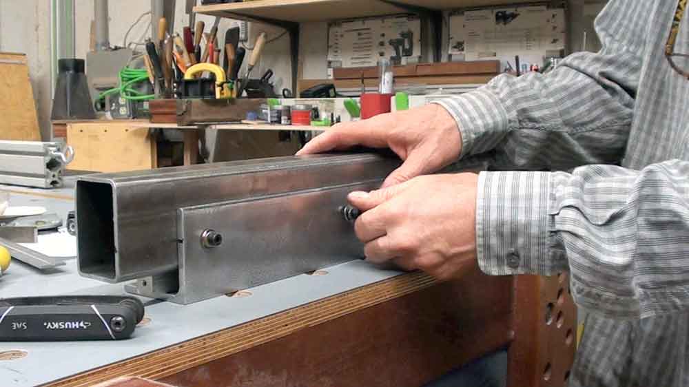
Bolt angle iron to rectangular tubing, check alignment fig.16a)
STEP 17: CHECK SPACING
Now double check your spacing using your 3/4” parallel spacing set up. You should have just enough play (lateral adjustment) in both directions to comfortably tighten the tubing in position with the 3/4″ spacer in place. (fig.17a)
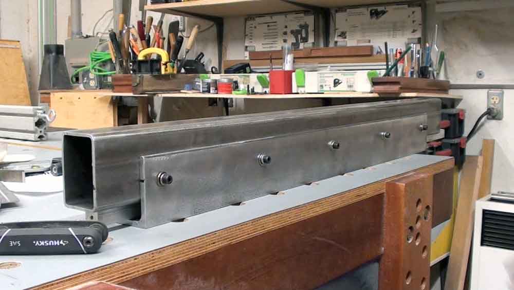
Checking your parallel spacing between angle iron and tubing (fig.17a)
STEP 18: DETERMINE CONNECTION LOCATION
Determine the connection locations on the table saw, bandsaw, or router table for the angle iron. (fig.18a)
Find and mark guide rail connection holes on your table (fig.18a)
STEP 19: DRILL HOLES INTO TABLE
Drill connection holes if necessary.
NOTE: You many already have holes in your table that you can use. (fig.19a)
Check for existing holes in table saw that you can use (fig.19a)
Making a solid table saw guide rail is the first thing to consider when looking to upgrade your saw.
STEP 20: CLAMP GUIDE RAIL TO TABLE
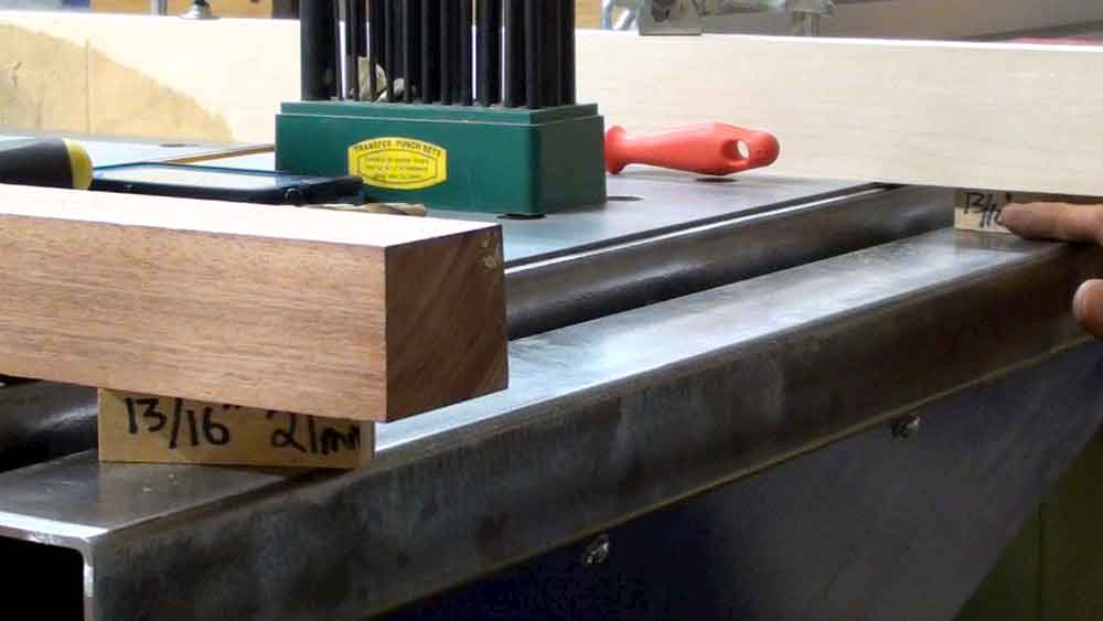
To hang the guide rail accurately in position you’ll need your step-down spacing set up. Two Milled, flat and straight, stout long boards and two small 13/16″ milled spacers. Cantilever the boards off the edge of the saw or table with clamps to hang the guide rail unit exactly 13/16” below the top of the table.
NOTE: This is the Biesmeyer standard step-down measurement. It must be exact. (fig.20a, 20b)
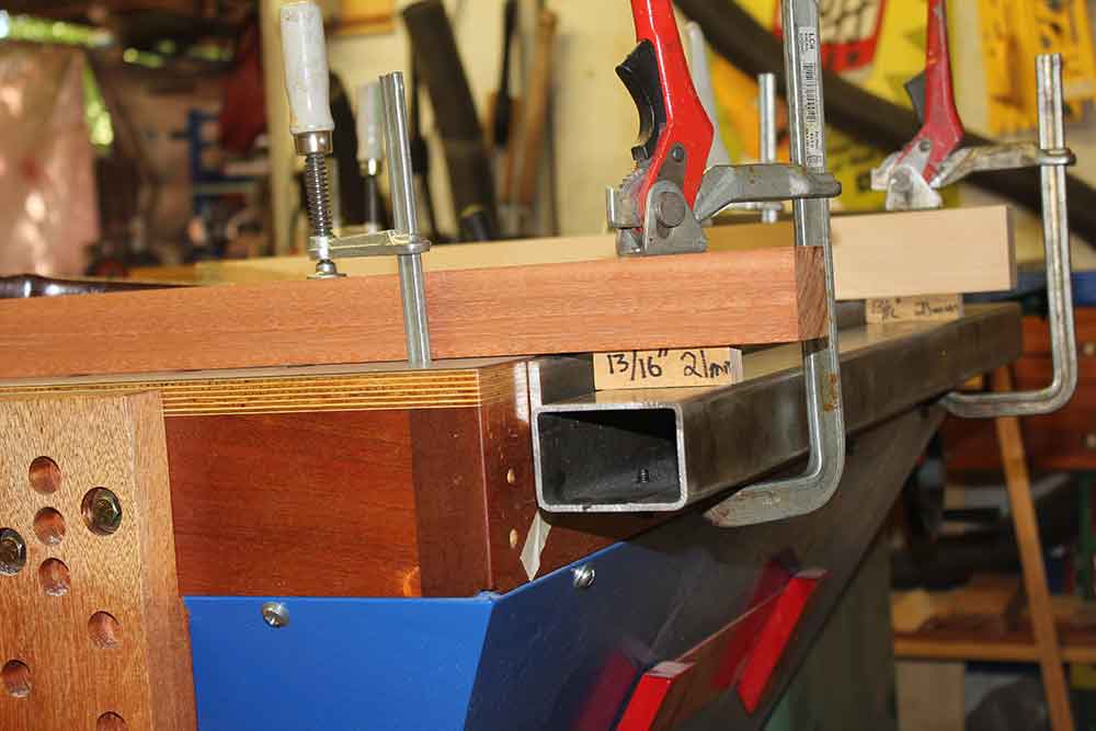
Angle iron and tubing clamped and hanging in place on table (fig.20a)

Close up, step down spacing to Biesemeyer guide rail specifications (fig.20b)
STEP 21: MARK HOLE LOCATIONS ON ANGLE IRON FROM TABLE
Use a drill bit the size of the connection holes, and a hand drill, transfer punch or a scribe to mark these hole locations on the back side of the angle iron. (fig.21a, 21b)

Marking from the back side through the table to the angle iron marking drill locations (fig.21a)

Holding the transfer punch used to mark hole locations (fig.21b)
STEP 22: UNCLAMP AND UNBOLT ALL
Unclamp guide rail from table. Then unbolt the tubing from the angle iron so that you can drill your holes. (fig.22a)

Unbolted angle iron with hole marks before drilling (fig.22a)
STEP 23: STEP DRILL HOLES IN ANGLE IRON
Take angle iron to the drill press and drill holes in the marked locations to 5/16”. It’s important to step drill (use two different sized bits). For the first hole drilling you will use a smaller bit (the same bit you used to make your drill marks). The second bit you use will be to size, 5/16″. FIRST DRILLING STEP: The angle iron is positioned upside down as you are drilling out the holes located on the back side. SECOND DRILLING STEP: You will flip the angle iron over because that’s the side you will be countersinking. (fig.23a, 23b)
Drill holes on the back side of the angle iron with small bit (fig.23a)

Flip the angle iron and drill out holes again with 5/16″ bit (fig.23b)
STEP 24: COUNTERSINK ANGLE IRON
Still at the drill press, you now take an 82 degree 3/4” diameter countersink and countersink the inside of the angle iron at these 5/16” hole locations to the proper depth (slightly below flush for the 5/16” flat head grade 8 bolts).
NOTE: I recommend clamping the angle iron while countersinking to stop bit chatter. (fig.24a)
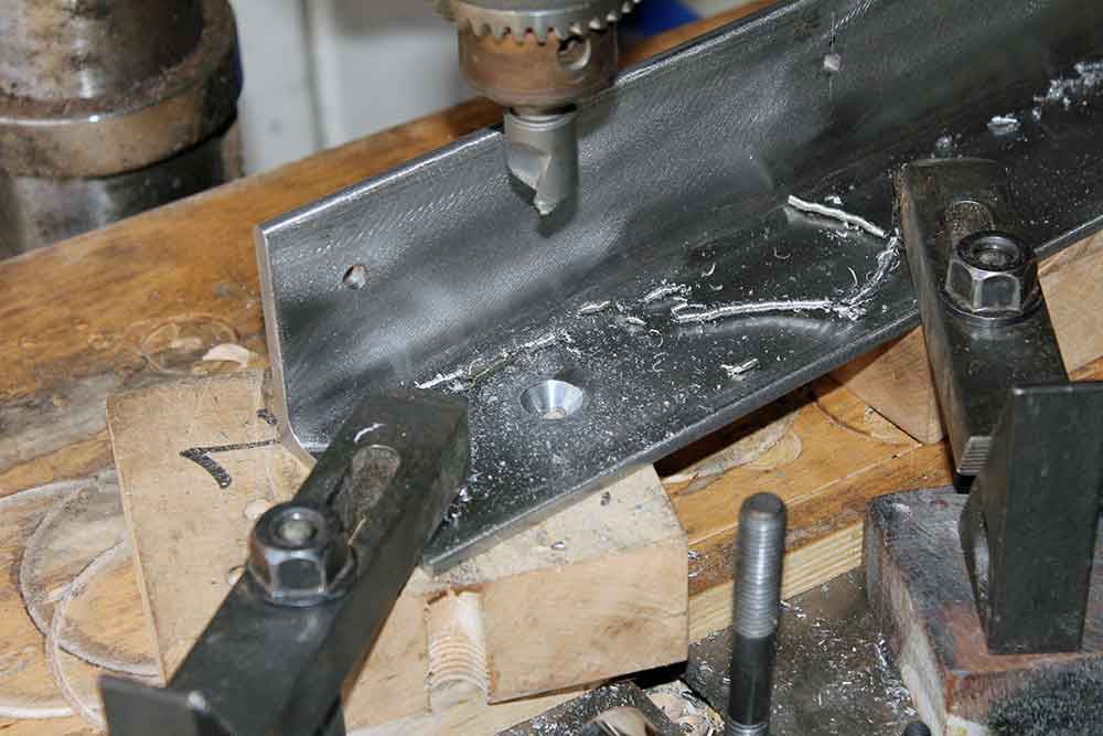
Countersinking 3/4″ diameter into angle iron at drill press (fig.24a)
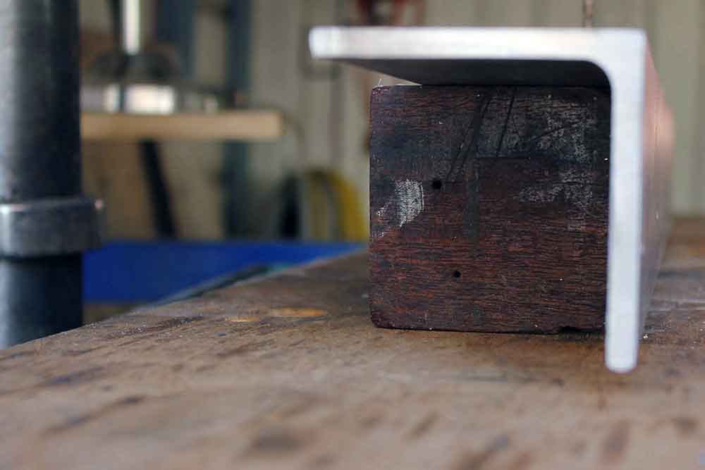
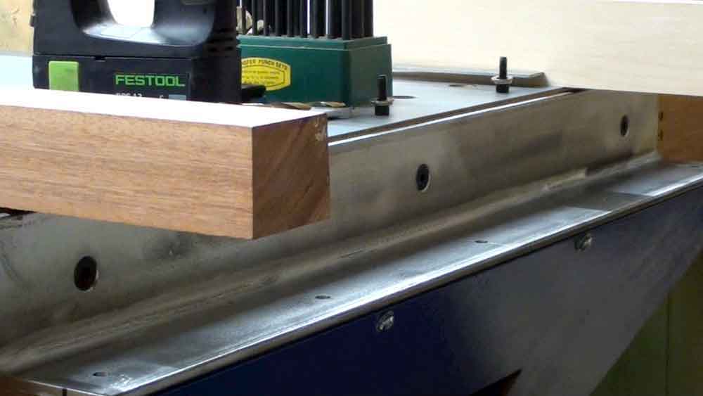
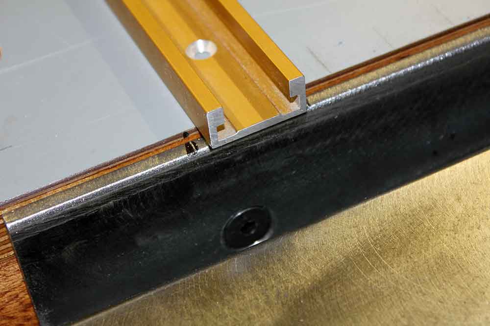
STEP 25: HAND DRILL TABLE HOLES
Drill out connection holes in saw or table to 11/32”. (fig.25a)

Opening up connection holes to 11/32″ using a square piece of wood for accuracy (fig.25a)
STEP 26: SLIDE BOLTS IN ANGLE IRON
First put all of your bolts through the holes of the angle iron. Then on to step 27. (no image)
STEP 27: BOLT ANGLE IRON TO SAW
Now connect the angle iron to the saw or table with your 5/16” flat head bolts. You may need to do additional drilling to the table holes to open them up a bit ( not the angle iron, leave those holes alone! )
NOTE: This is just a test for alignment so don’t tighten too much when attaching. (fig.27a, 27b, 27c)
Bolting angle iron to the table for the first time (fig.27a)
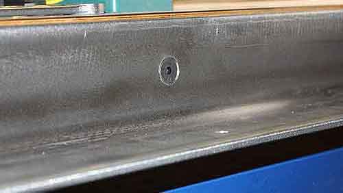
Close up of countersink bolt in angle iron (fig.27b)
Bolts in angle iron are lightly tighten before attaching tubing (fig.27c)
STEP 28: BOLT TUBING TO ANGLE IRON
With your angle iron in place, use both of your spacing set ups; 3/4” parallel spacing bar w/lifts and 13/16″ step-down blocks to position your tubing. When you are sure of position, bolt your tubing in place. (fig.28a)
Bolting tubing to angle iron with both spacing set ups in place (fig.28a)
STEP 29: TIGHTEN AND CHECK FIT
Now tighten connection bolts securely through angle iron and table and double check for final fit. Make sure both your parallel gap and your step-down spacing are accurate. (fig.29a)
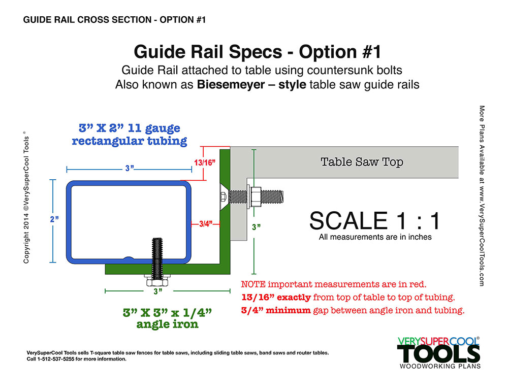
Cross section drawing of Biesemeyer style guide rail (fig.29a)
“Whether you have a new saw or an older model, many times the only thing keeping your saw from being a great saw is a proper table saw guide rail.”
STEP 30: MARK MITER CUT OUTS
If fit is correct, mark miter slot cut out location. (fig.30a, 30b)

Miter slot positioning and layout for router table (fig.30a)
Marking where to notch out the miter slot in angle iron (fig.30b)
STEP 31: UNBOLT EVERYTHING!
Unbolt the angle iron from the table and the tubing from the angle iron. (no image)
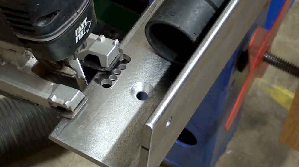
STEP 32: CUT MITER SLOT
Cut out notch in top of angle iron for miter slot. I drill a perforated pattern with my drill press to define the edge boundaries, then use the jig saw and a bimetal jig saw blade to complete the notch. (fig.32a, 32b, 32c)
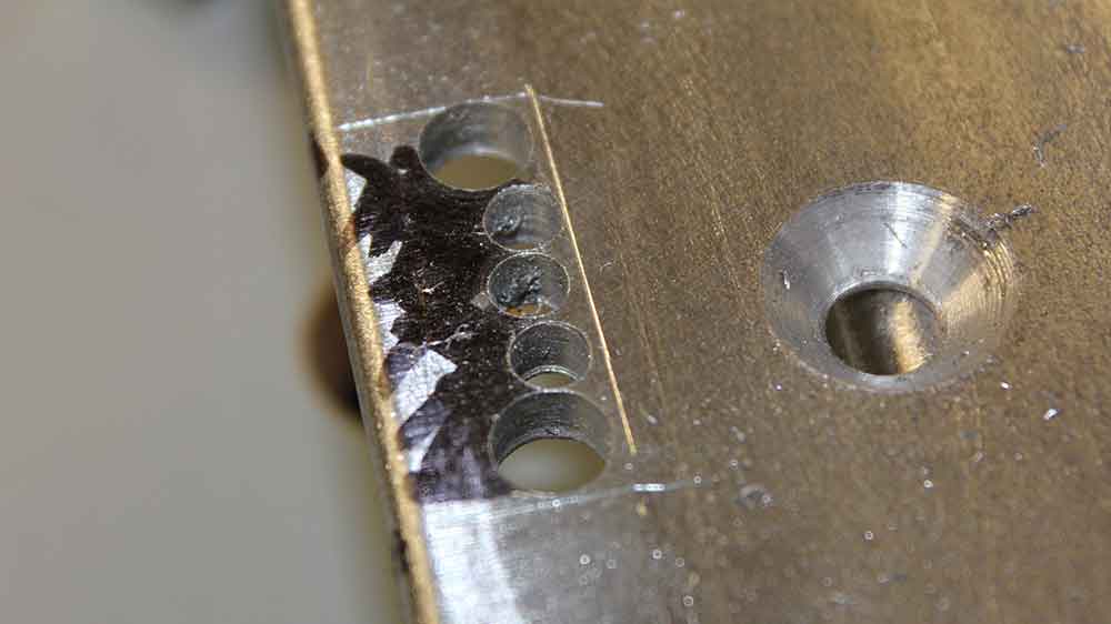
Drilling holes (perforations) in miter slot marked area (fig.32a)
Cutting out to scribed line with jig saw with bimetal blade(fig.32b)

Rough cut out of miter slot before filing and sanding (fig.32c)
STEP 33: SOFTEN EDGES
Use a file on the miter notch edges and then soften with course scrap sandpaper. Sharp edges are harder to paint. (fig.33a)
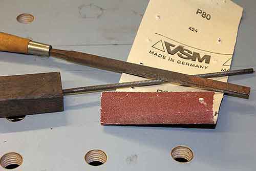
VSM 80 grit sandpaper, files for softening miter slot (fig.33a)
STEP 34: CLEAN WITH MINERAL SPIRITS
Clean angle iron and tubing with mineral spirits and a green Scotch-Brite Heavy Duty scouring pad. Wipe with clean rag before priming. (fig.34a)
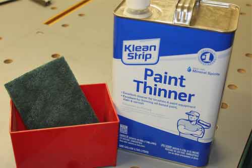
Green scour pad and a can of paint thinner (fig.34a)
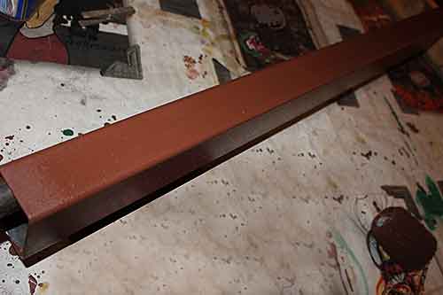
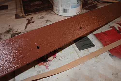
STEP 35: PRIME
Prime with high quality metal primer. I like Sherwin Williams Kem Kromik. (fig.35a, 35b, 35c)
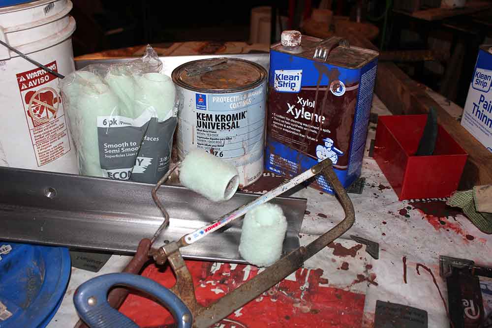
Rollers, rags and Sherwin Williams primer. (fig.35a)
Primed rectangular tubing for guide rail (fig.36b)
Primed angle iron for guide rail (fig.35c)
STEP 36: PAINT
Paint with high quality paint. I like Sherwin Williams Sher kem. They have some great bright colors. (fig.36a, 36b, 36c)
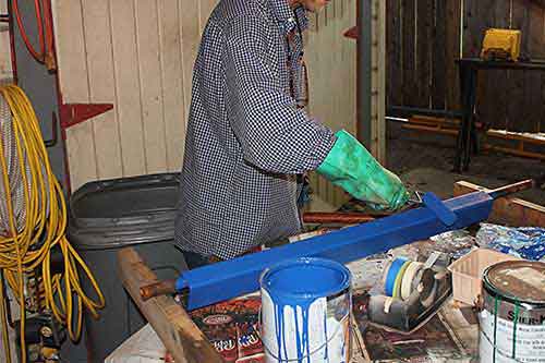
Painting the rectangular tubing blue with a foam roller (fig.36a)
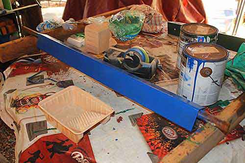
Guide rail tubing painted with blue Sherwin Williams paint (fig.36b)
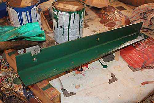
Guide rail angle iron painted with green Sherwin Williams paint (fig.36c)
STEP 37: CLEAN PAINT FROM THREADS
Use the 1/4″ 20 TPI tap in a cordless drill to clean paint from threads. (fig.37a, 37b)
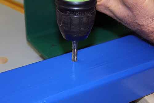
Close up: cleaning out paint from thread using drill (fig.37a)

Using hand drill with 1/4 20 TPI tap to clear holes of excess paint (fig.37b)
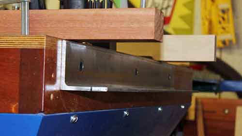
STEP 38: BOLT ANGLE IRON TO SAW – ( Not Too Tight! )
Bolt the angle iron alone to table saw. It needs to be secure but a little loose. You will be making some micro adjustments in the last step. (fig.38a)
Final attachment of the angle iron to the table, don’t fully tighten yet (fig.38a)
STEP 39: BOLT TUBING TO ANGLE IRON – ( Tight! )
Bolt the tubing to the angle iron for the last time, using your parallel spacing set up. (Step-down spacers not needed yet.) Do your final tightening now!
NOTE: Very important to do this step BEFORE final tightening of the angle iron to the table because you will need to remove your parallel spacing setup. (fig.39a)
The final bolting of the tubing to the angle iron (fig.39b)
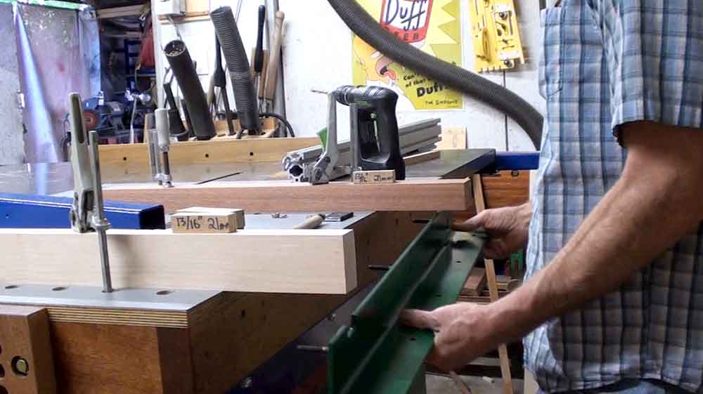
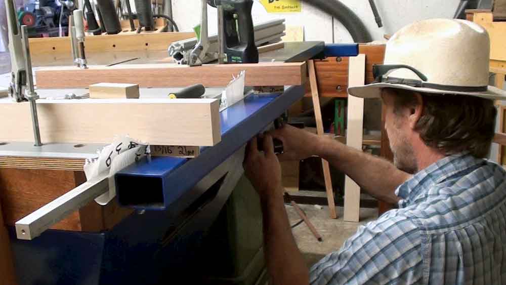
STEP 40: FINAL ANGLE IRON PLACEMENT – ( Tight! )
Get your step down spacing set up in place; Four clamps, two long boards and two small 13/16″ blocks. Position the angle iron and tubing unit into final position using your clamps. When final position is achieved, do your final tightening of the angle iron to table.
NOTE: Parallel spacing bar is removed for your final tightening so you can easily check the bolts and make sure they aren’t spinning. (fig.40a)
FINISHING TOUCHES: Congrats you are done! All you need to do now is to attach the tape measure to the tubing! (video below)

Final install of table saw guide rails (fig.40a)
How To Make Your Own Guide Rails
Below is the companion video playlist for this 40 step blog post.
How To Accurately Attach Your Tape Measure
The adhesive is permanent. You only get once chance to get it in place perfectly.
I have made several sets of guide rail for myself and others. Below are the three guide rail setups currently in my shop. I don’t have the router table finished, but I have the rails made.
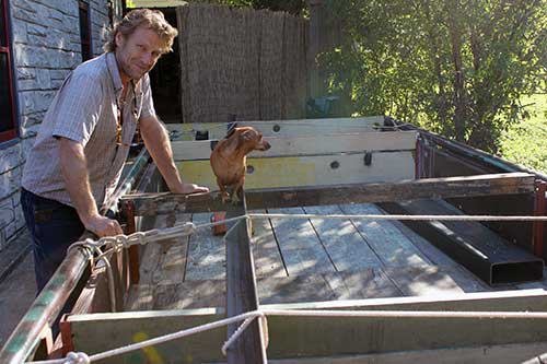
Table Saw
Allan Little (AskWoodMan) with his table saw with shop made guide rails.
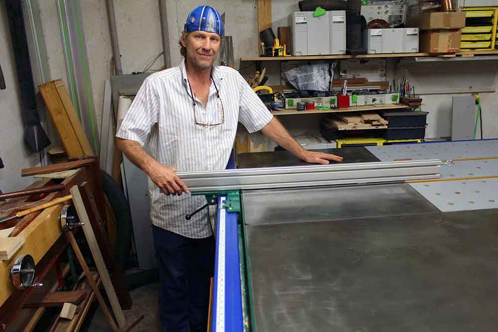
Table saw with VerySuperCool Tools t-square with aluminum extrusion fence.
Router Table
Allan Little at his router table (router not dropped in yet) with shop made guide rails.
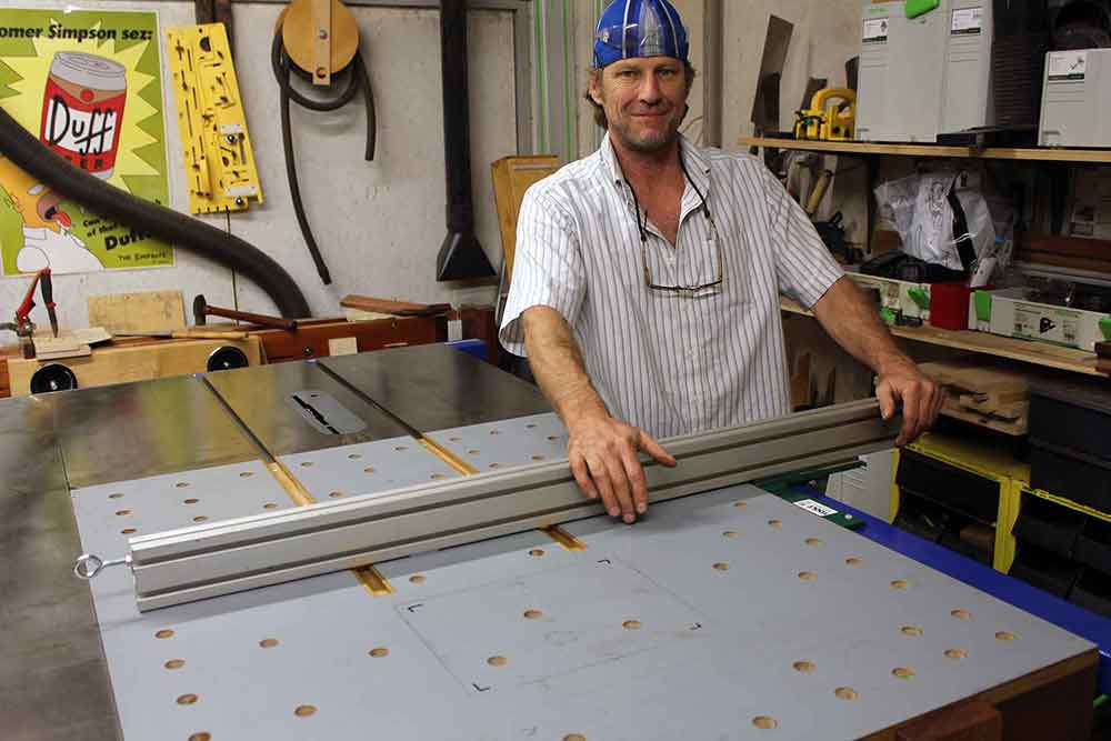
Router table with VerySuperCool Tools t-square with aluminum extrusion fence.
Bandsaw
Allan Little (AskWoodMan) at his bandsaw with shop made guide rails.
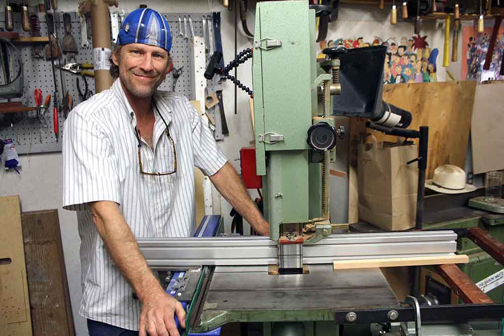
Bandsaw table with VerySuperCool Tools t-square with aluminum extrusion fence.
Great step by step guide here. About to have a go at home. Here goes !!
I Like your job Bro.
i will make one like yours. actually i bought Jet table saw from a local market with very cheep price, actually the local distributor bought for some one but order was cancelled so he kept the saw for 2 years with him and then he was willing to sell on any price so i offered and i got it.
The rails Assembly was missing in it but any how it was a good deal so i thought to buy or make one for me.
the price of the machine is 4000 $ but i bought it for 900 $.
Bro. what do you suggest me to make one or buy the genuine ?
and i live very far from US . i live in United Arab Emirates.
but i really enjoyed with your work and your step by step demonstration it is really very easy to do it by yourself.
wish you the best.
Regards
Hamad
Great job. well done
Thanks. I hope it helped you with your guide rail build!
BS low – ratitnalioy high! Really good answer!
Hi there,
Just wondering, as I don’t really know much about metal working, what’s the reason for using steel and not aluminum for the guides?
Thank you!
Hi Jose,
Aluminum can’t take the abuse like steel can. And using steel bolts in aluminum would wallow out your holes. Plus aluminum ends up being about four times more expensive. You’ll have better guide rails and spend less money if you make them out of steel. Plus they are easier to work.
Good luck with your build.
Allan
Thanks for inoncdutirg a little rationality into this debate.
Very nice. I’ve been looking for a long time for this kind of info. Thank you.